Removing a Reliant engine from the donor car |
This information is produced purely as an aid. In all issues of safety and mechanical procedures, reference should be made to the appropriate manufacturer’s literature. Sections in ‘Bold’ format, plus illustrations, are taken from the ‘Haynes”, (Robin & Kitten), workshop manual 1973–1983. Sections in Italics, plus additional photos, comprise my thoughts and observations.
2. Remove the bonnet to allow easier access and aid in removal of auxillary engine compartment components during engine removal. 3. Remove all the ‘in-car’ heating system tubing in the engine compartment to aid access. 4. Drain the engine cooling system, (engine cold).
If the engine has been running, be aware of the possibility of hot liquids and take appropriate safety precautions.
6. Refit the sump drain plug.
9. Remove the air cleaner, (filter). 10. Slacken the securing clip and disconnect the heater hose at the water pump. 11. Slacken the securing clip and disconnect the heater hose from the manifold adaptor mounted on the inlet manifold and release it from the mounting bracket located on the rocker cover stud.
13. Remove the alternator. It’s not really necessary for the alternator to be removed, although the plug still needs to be disconnected.
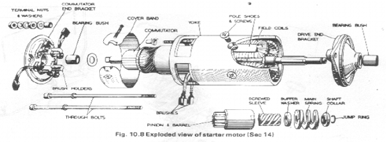
14. Remove the starter motor, (assuming the battery is disconnected).
15. Disconnect the lead from the coolant temperature sender unit at the thermostat housing. 16. Disconnect the lead from the oil pressure sender switch on the right-hand side of the engine block or if a gauge is fitted disconnect the oil pressure pipe. 17. Disconnect the HT and LT leads from the ignition coil. 18. Working inside the vehicle, remove the centre console. Most trike builders need not be as fussy as the typical Reliant enthusiast about carefully removing parts not re-usable as trike building spares in one piece, so just rip the bugger out if you’re not going to use it again.
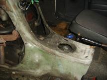
There’s a rear access panel in both passenger-side and driver-side foot wells.
21. Disconnect the throttle cable at the carburettor, (on 850cc engines release the cable from the bracket on the carburettor). 22. Disconnect the choke cable from the carburettor.
24. On 850cc engines only:
The exhaust is easily removed by cutting through the rear leather support strap, accessed via the rear wheel arch.
28. Disconnect the propeller shaft from the gearbox rear-coupling flange by removing the four bolts. Access to these nuts and bolts is restricted by the gearbox rear mounting bracket and quite awkward, with access to only 2 of the 4 nuts/bolts at a time, due to the rotation of the driveshaft. The driveshaft needs to be rotated through 180 degrees to access the other two nuts/bolts. Impossible if the front of the vehicle is jacked up. This can be overcome by disconnecting the driveshaft to axle differential coupling, allowing the driveshaft to be turned to the required position. Of course there’s always one awkward nut/bolt that won’t come loose and it’s usually one of these. It may be easier to cut through the gearbox cross-member, either side of the gearbox rear support bracket, allowing the engine/gearbox to be lowered while still attached to the driveshaft, (because the driveshaft runs above the cross-member). The driveshaft/diff. coupling can then be disconnected and the engine/gearbox supported with a jack to prevent dropping and damage as required in step 29.
31. Make a final check to ensure that everything necessary has been removed or disconnected and that all electrical wiring and cables are tucked out of the way where they will not get caught up while the engine/gearbox is lowered.
Lots of ‘jiggling’ and manoeuvring, but the lump will eventually come out.
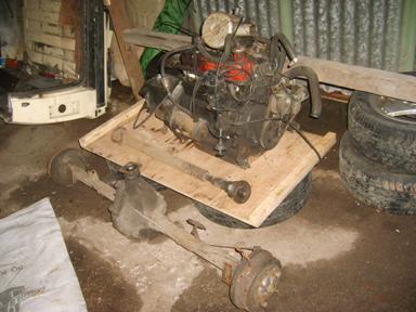
33. The engine and gearbox can now be separated by removing the two top bolts and six nuts which secure the gearbox to the engine crankcase and withdrawing the gearbox. Take care not to put any strain on the gearbox input, (primary), shaft when withdrawing the gearbox. The rear axle cam be removed by disconnecting the shock absorbers, disconnecting the hand-brake cable and brake-pipes and unbolting the four U bolts which hold the leaf springs. Ta-daa !
One set of Reliant running gear, all set for it’s new home in your trike frame. -Dicky |
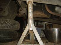
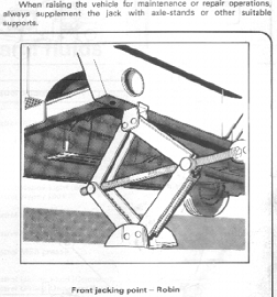 1. Chock rear wheels and lift the front of the vehicle and support on suitable blocks or stands.
 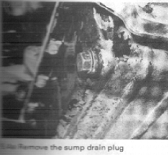 5. Drain the engine oil by removing the engine oil filler cap and sump drain plug. Catch the oil in a suitable container of at least 6 pints, (3.3 litres), capacity.
 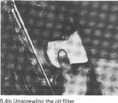 7. Unscrew and remove the oil filter.
 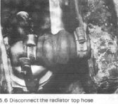 8. Slacken the securing clips and disconnect the radiator top hose from the thermostat housing and the bottom hose from the water pump.
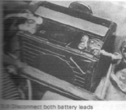 12. Disconnect the battery.
 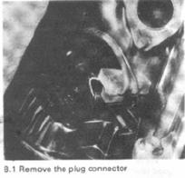 Release the spring clip and pull out the plug connector at the rear of the alternator.
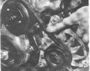 Push the alternator towards the engine and take the drive belt off the alternator pulley.
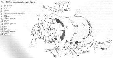 Remove the adjusting and mounting bolts and spacers, then lift out the alternator. Note the location of the spacers.
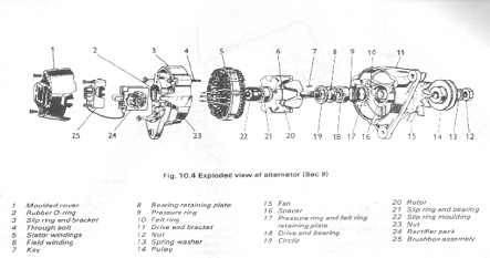
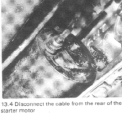 Disconnect the starter motor cable from the terminal on the starter motor end plate.
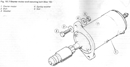
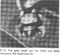
 19. Prise out the spring retaining clip from the gear lever ball-joint cap on the gearbox top cover and lift out the gear lever.
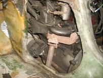 20. Undo the six securing screws and lift away the rear access panel.
 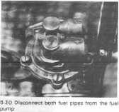 23. Disconnect the fuel inlet and outlet pipes from the fuel pump and plug the openings to prevent loss of fuel and ingress of dirt.
 25. Release the clutch cable from the clutch operating arm, remove the locknut and adjusting nut and withdraw the cable from the trunnion. Pull the clutch cable outer sleeve from its seating in the engine backplate.
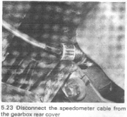 26. Unscrew the knurled securing collar and disconnect the speedometer cable from the gearbox rear cover.
 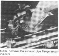 27. Undo the nuts securing the exhaust down pipe to the exhaust manifold and to the support bracket, then drop the pipe and move it to the side.
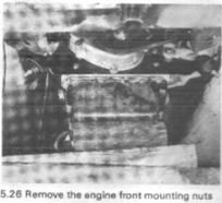 29. Unscrew and remove the two nuts securing the engine front mounting rubbers to the engine mounting brackets on the chassis.
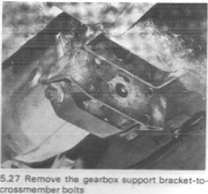 30. Support the engine/gearbox assembly by positioning a jack under the engine sump, using a block of wood between the jack and the sump to spread the load. Remove the nuts and bolts, (four on models with a 750cc engine, three on models with an 850cc engine), attaching the gearbox support bracket to the chassis cross member mounting. Note the earth strap attached to one of the bolts.
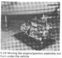 32. With a rope sling around the front of the engine, raise the engine slightly and pull it clear of the front engine mounting brackets, then lower the jack, supporting the rear of the engine manually. Lower the engine/gearbox assembly, preferably onto a wheeled trolley, and remove it from beneath the vehicle.